Monday, November 21, 2011

A lower power LED blinker

There have been a number of changes to this circuit since i started, and it looks like i should really re-design my LED blinking circuitry before going much further.The biggest change was switching from two 1.3V battery cells in series, for a system voltage of 2.6V, to one or two batteries in parallel, giving a system voltage of 1.3V or so. To reach a charging voltage of 2.6V i was going to up-convert my coil voltage to 5V with a boost converter, and use that to charge the batteries. Ive since changed all of that, and now charge my batteries directly from the coils at 1.3V. I still have a boost converter after the batteries, as all of my LED drive circuitry was designed for 5V operation.

What i'm hopping to do is remove the boost altogether, and just run everything off of a single cell voltage of 1.3V.  This is quite do-able, but will mean a re-design of the LED circuitry. Additionally, new parts need to be found that can operate with a 1V supply rail.

LTSpice simulation for my new oscillator
The first part to replace is the 555 Timer that i'm using as an oscillator. Its hard to find a version of this chip that can operate at such a low voltage. Additionally, i don't need all the capabilities of a 555, i just need an astable circuit. One of the simpleness ways to do this is with a Relaxation Oscillator, built using a comparator or an op-amp. Since i only have a single supply rail my circuit is slightly different than some. Ive basically just added a voltage divider (R1 and R2) to re-zero the input so that everything works as expected. This seems to work fine... so ill use it. The benefit here is that the MAX4289 op-amp that i'm using can run off of a 1V supply, while the 555 i was using needed 3V or so. Additionally, its much simpler.

Oscillator output, with the load varied between 100kOhms and 1kOhms
I tested the designed oscillator with a few loads, just to make sure that I wont have to add a buffer stage to its output. It looks like as I swept the load between 100kOhms and 1kOhms (13uA to 1.3mA) the oscillation frequency only changed slightly. This is OK, so ill just use the circuit as-is.

The rest of my logic (to make the LED's blink in two different patterns) can be slightly simplified, but ill use basically the same chips. Currently I'm using the NC7S family, which needs at least 3V supply voltage, so ill just switch to the NC7SP family of chips, which can run off of 0.9V. The revised schematic looks something like this,
New Schematic using 1V logic.
Here, the boost converter just drives the LED's, while everything else is 1V logic. To deal with this, i may also need to change the LED string switches (U7 and U9), so I'm ordering some low voltage MOSFET's just in case i need to replace the BJT's I'm using now.

I went ahead and modified the old layout as well, here is an updated version.
New layout to go with the new schematic.
Ive made a few important changes here:

  • There is only a single battery now, so the majority of the layout sits on top of this. This is about as small as this design will get as long as I'm using a AAA battery. 
  • The controlling switches have been moved to the LED board, so they will still be accessible if i decide to put the battery in the seat post as I've been planning.
  • Finally, the LED board itself has a new shape. I measured the back of my current bike seat, and if everything goes well this new shape should fit nicely between the rails at the back of the seat.

Thats about it. Ill send for the new board today and order the parts in the next few days. If all goes well i should get the new boards back next Monday or so.

Friday, November 18, 2011

Coil Voltage Rectification

Until today, I've setup my two power generation coils in series with a full wave rectifier connecting them to the batteries. Something like the schematic below:
Two Series Coils with a Full Wave Rectifier

This is an OK setup in most situations. It lets us harvest energy from both the positive and negative spikes of voltage in the coils. Additionally, the series coil setup is the only one that makes sense if the coils are not going to be excited by the magnetic field at the same time. So everything should work fine.

The issue is that the full wave rectifier means that the coil voltage is reduced by two diode forward voltage drops before its gets a chance to charge the batteries. These forward voltage drops are anywhere from 0.7-0.3V. I specifically chose my diodes to have a small voltage drop, but when you are only dealing with a 1.3V battery voltage, a voltage drop of about 0.5V is a big deal. So using a half wave rectifier may be a better choice. In this case, you only get to harvest the positive voltage spikes, but you get more out of them, as there is only a single diode drop. This setup would be something like this:
Two Series Coils With a Half Wave Rectifier

So i ran some tests today to compare the two approaches. My prototype board was setup originally to make these specific tests easy, so not too much work was involved. These tests where taken at what would be a decent pace on my bike. Here are the results.
Series Coils With a Full Wave Rectifier
Series Coils With a Half Wave Rectifier
It looks like either choice is OK. Although we are getting less frequent current spikes into the batteries with a half wave rectifier, we are getting much more current per spike (almost 18.5mA peak vs. 12mA peak), for a comparable average charging current (1.5mA vs. 1.45mA). Since the full wave rectifier needs larger voltages, it works better for charging at higher wheel speeds, while the half wave rectifier will charge at lower speeds. Apparently in the middle it doesn't matter. As i'm more likely to go slower on average around town rather than faster, ill change my coil setup to have a half wave rectifier.

An additional issue is the coil resistance. This was touched on in my last  post, but its practical implications where mostly ignored. I'm using very thin wire so i can get the size of my coils down while still using lots of turns. Thinner wire has a larger resistance per meter, and since i'm using so much thin wire, i end up with about 35Ohms of resistance per coil. In a series connection, the coil being excited by the magnets has to drive the resistance of the other coil, as well as the rectifier diodes. This means that as a magnet passes a coil, you end up with the situation seen below.
Equivalent Circuit During Coil Excitation 

Needless to say, this is not ideal. In addition to a voltage drop you have a relatively large resistor in the way. A better solution may be the one below.
Improved Half Wave Coil Setup
Originally i wasn't sure that a half wave vs a full wave was going to make much of a difference and i didn't want to put two full wave rectifiers on the board, so i ignored this setup. But since I'm going to use half wave rectifiers anyway... i thought i might as well give it a shot.
Two Coils With Dual Half Wave Rectifiers
With the same test as before, this setup behaves better. we are up to almost 2.5mA charging current, which is really quite good. Note that to set this up on my board, i inverted one of the coils, which is why it looks like I'm harvesting positive spikes from one coil and negative spikes from the other. This will probably be my final design for the coil rectifiers. I'm glad i took a look at this as the changes made almost doubled my available charging current.

Tuesday, November 15, 2011

Number of Turns, Revisited.

The number of turns that i estimated on the new coils doesn't seem quite right. which it probably isn't as for the most part its was a complete guess. I thought it may be interesting to put some bounds on this number and do some estimation, so here we go.

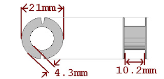
The bobbins that I'm using have a window area of about 44mm^2. This is a measure of how much area for copper the coil has. Here, its found by multiplying 4.3mm and 10.2mm. Since the wire i'm using has a diameter of 0.16mm, it has a cross sectional area of 0.02mm^2. This means that at most there could be 2200 turns on this bobbin, probably less. This would be the case if there where no air gaps in between wire, which is impossible as the wire is round. More reasonably, we could look at if the wire a lined up in a grid, each piece sitting on-top of each-other for the maximum airspace. this would give us about 1700 turns. So if i wrapped this perfectly, i would have between 1700 and 2200 turns per coil. Of course i didn't wrap this well, so it's probably much less than this.

When wrapping magnetics, people usually use a scale factor called the "fill factor", or "window utilization factor". This term approximates how much of the window area is actually filled with  copper, vs how much is filled with air due to gaps between turns. This is a percentage, where a fill factor of 0.9 means that 90% of the window area is used by copper, with the remaining 10% filled with air or insulation, etc. The fill factor can vary between about 0.05 for high voltage transformers with lots of isolation between wires, and about 0.5 for a simple hand wound inductor. Using special materials like a foil instead of wire (which rips all the time and is just horrible to work with), or square wire (which is a pain to wrap) can get this number up to about 0.65. For this coil, 0.3 is about the worst reasonable, which gives us 660 turns as a lower bound.

Putting this together, ill use 1700 as an unreasonable upper bound, and 660 as a lower bound. its a decently wide range, but lets me know that i have way more turns than i expected, which makes sense due to the much larger voltages that i was getting.

As a double check, we can measure the resistance of the wires. The inner winding radius is 6.2mm, while the outer is 10.5mm. This gives us an average of 8.35mm, which ill bump up to 9mm because if how things are wound on the bobbin. This leaves us with an average turn length (amount of wire used on each turn) of about 56mm. At room temperature, AWG34 wire has a resistance per meter of about 0.86Ohms. The coils i wound have resistances of 38.1Ohms, and 34.3Ohms, giving approximate number of turns of about 790 and 710 for the two coils. This makes sense, as one gives a slightly higher voltage spike than the other.

So that was fun.

New Coils - Finishing the Prototype

 The new coils for my prototype boards are finally done! Using two old PQ cores, i wrapped as many turns as i could of AWG34 wire. This should be about 4-500 turns based on some old tests, which should give me a reasonable voltage on the output. Using some old plexiglass that we have laying around, i'm going to make a coil holder to make the tests easier. The coils are in series, and i'm planning on placing them so that they are individually excited by the magnets.  Some old tests showed that  if they are excited at the same time, its hard to make sure they don't fight each other. So i'm hoping to avoid the issue altogether. heres a picture of the coil holder as i'm planning on cutting it out...
...and here is the final product... 
 In the end, ill use a laser cutter to get the right shape to mount this to my bike and make things a bit cleaner, but for now this is OK. The wire to the battery holders runs through this holder twice, mostly just to remove any strain on the connections when i'm moving this thing around. After adding some test-points which i initial forgot and fixing my diode rectifier which i messed up at first,  i was able to get some test results with the setup below.
The raw coil voltage is measured using a single ended passive probe, while the rectifier output is measured with an active differential probe. This is needed as the two sides of the rectifier have different ground references. Using a single ended probe on bot sides of the rectifier effectively shorts the grounds together through the scope. At high power levels, this doesn't make the scope happy, while at low power levels like in this circuit, it can simply mess-up the measured signals. Below, the coil voltage is seen in yellow, while the rectifier output is seen in purple.

Note that although the rectifier output says it has units of amps, it really is volts. (The diff probe i'm using doesn't like the scope i have, so the gains are messed up. Telling the scope your measuring current lets you fix this, just with the wrong units.) These waveforms are taken at about 6 or 7mph, and already we are getting 1-2V outputs! This is great, and really gives me more flexibility in the next revision. (The rectifier output is clamped at a bit above 1V, as its diode connected to the batteries. Voltages above this charge the batteries.) Additionally, you can see from the yellow coil voltage waveform that i placed the coils just barely to close together. It should be fine for now, but ill fix it eventually. you can also see that the first coil has a few more turns on it (higher spikes) than the second. This is also not an issue, and one i don't care about anyway as both voltages are high enough.

Next up, i need to make sure that the battery charging currents are reasonable, and then double check that i'm generating enough power with these coils to make this system self sustaining.

Monday, November 7, 2011

Complete First Revision

I finally got around to populating the boards. Everything seems to work well. The LED's are attached with a 12" wire, while the coil board is attached with a 6" wire. After a bit of trouble getting the correct blink frequency, it looks like this is a working bike light! I still need to do all the power measurements and such to make sure everything will work in the long run, but for now its nice to have a working board together.

I took a short video of the lights working, showing the different light modes. I balanced my phone on my coffee cup to get the video, hence the poor quality. In any case it does show things working.